A lot of folks get confused when it comes to keeping Air Conditioning when doing an LS engine conversion, or any engine conversion for that matter, in a Z32 300ZX. The misconception is that the factory ECU controls the AC Compressor Clutch, so if it is removed, the AC can not function. LOJ is here to tell you that isn't true, explain why, and explain exactly what you need to do to remove the ECU from the equation when it comes to AC control in a Z32 300ZX.
While it is true that the AC Relay trigger wire is signaled by the Nissan 300ZX ECU, that is done for a specific set of reasons. This is the factory logic:
- Driver sets climate control to a setting that would require AC compressor operation.
- "Auto/Manual Climate Control Amplifier" interprets signal from climate control panel and outputs request signal to ECU. This is a switched ground signal.
- ECU receives signal, then evaluates a number of engine parameters. I.E. Throttle Position, Engine Coolant Temp, Engine RPM, etc... and determines if the engine is at an acceptable load level to support AC operation.
- If conditions are correct, ECU sends signal to AC Relay through AC pressure switch. This is a ground signal. As long as pressure in the AC line is within acceptable limits, the ground signal will get through the pressure switch to the relay and trigger the compressor.
- ECU simultaneously raises the engine idle to compensate for the increased load.
- As pressure in the high-side line increases, the pressure switch handles cycling the compressor based on thermal load.
- Additionally, the ECU evaluates vehicle speed and can turn on the Aux Cooling Fan to assist the cooling of the condenser at low vehicle speeds. On TT models, it can do this in two speed stages as the TT fan is a dual speed fan.
If you would like the AC Relay trigger function to take place independent of the ECU, then we need to remove the ECU from the equation above. Since the signal to the ECU from at AC Amp is a ground signal, and the signal from the ECU to the Relay is a ground signal, we can simply bypass the ECU. Now whenever the AC Amp is requesting the compressor to function, it will.
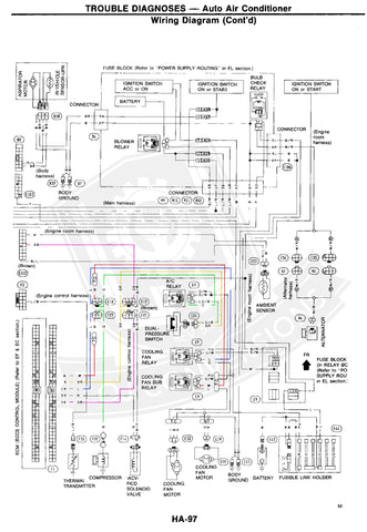
Take a look at the following wiring diagrams, these images are courtesy of Nissan and have been modified by LOJ Conversions for illustration purposes. (Click on images for full size view, this will open a new window)
Please note the above diagram is from a 1994 FSM, indicated wire colors may vary year to year, but the positions within the connectors will remain the same.
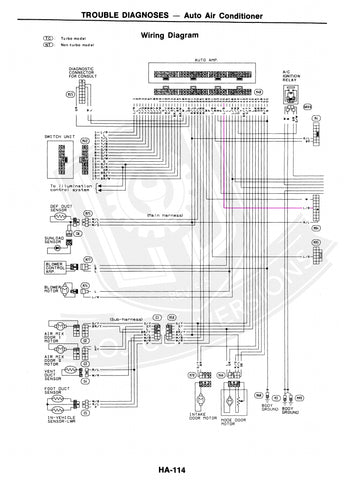
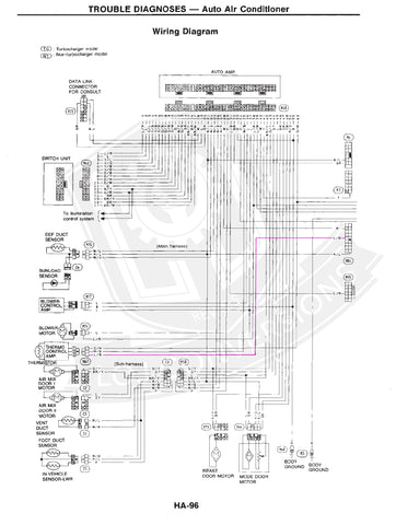
Notice the Pink wire labeled "SB" originating from the E112 connector. This is the AC request wire from the AC Amp. Look at the following two diagrams to understand where this signal comes from. 1991 first, 1994 second, both Automatic Climate Control systems.
Later models with Auto Climate Control and all Manual Climate Control models have a "Thermal Control Amp" wired between the AC Amp and the ECU. This has no bearing on the wiring method used to accomplish AC operation.
Notice the request wire passes through the E12/F25 junction and heads to the ECU. The ECU then outputs a signal over the Yellow wire labeled "OR" that passes back through the E12/F25 junction and heads to the AC pressure switch, then out of the pressure switch to the AC Relay via the Green Dashed wire labeled "LG/B".
What we need to do is bypass the ECU portion of this electrical pathway. The easiest way to accomplish this is to cut the F25 connector off of your VG30 Engine Wiring Harness. This connector is the 8-Pin plug that is located at the engine bay fuse/relay box on the drivers side of the engine bay. If you have elected to use the LOJ Conversions Swap Wiring Harness (You should, it's awesome), then you don't need this connector from your factory harness anyway. Once you've got this connector cut off (leaving yourself a couple inches of wire) you can de-pin and remove every wire from it with the exception of the "SB" (Pink on the diagram) and "OR" (Yellow on the diagram). Now connect these two wires together, heat shrink/solder, crimp connector, whichever method you are most comfortable with. Then reinstall the plug at the fuse/relay center.
Now what you need to do is get the 12V signal to the compressor to actually turn the clutch on. This is the second easiest part aside from the work you just did above. Notice on the wiring diagram that out of the AC Relay comes a Green wire labeled "G". It passes through the E10/F23 junction and then on to the AC compressor. The E10/F23 junction is the 6-Pin Grey connector right by the fuse/relay box in the engine bay. Cut the F23 connector off of your VG30 harness and cut the F22 connector (the actual compressor plug) off of the VG30 harness as well. Using these two connectors, splice a piece of wire in between to connect the Green wire at the F23 connector to the compressor via the F22 connector. If you have no desire to reinstall or control your factory AC Sub-Fan you're done, congratulations! You can de-pin and remove all other wires from the Grey F23 connector and call it a day. If you do want to reinstall and control that fan, read on...
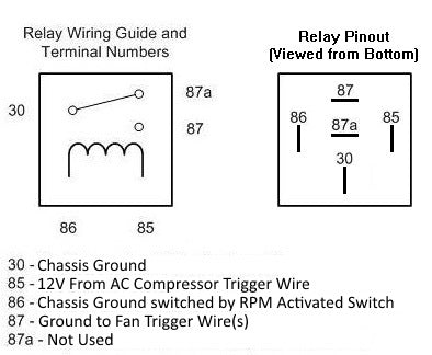
Notice the Blue and Red wires on the above diagram labeled "L" and "W" respectively. These wires go from the ECU through the E10/F23 junction to the fan relays. These are the trigger wires for the Sub-Fan. Single speed for NA and dual speed for TT. Leave these wires in the F23 connector and connect them to ground any time you want the fan to be on. Unfortunately there is no way to make the operation of this fan automatic without installing a RPM dependent switch, a relay, and routing a ground signal to these wires through the switch and relay. You can use a relay with the Normally Closed side of the RPM switch and the 12V compressor clutch trigger wire to make this function automatic. Using a standard automotive relay, wire it according to the following schematic.
As you can see, the Relay will only send the ground signal to the fan relays when the engine RPM is below the set point you choose (recommend 1500RPM) and if the AC compressor is on.


